
A UML sequence diagram shows how actors and system parts exchange messages over time to accomplish a goal. It is especially useful for turning a use case into a concrete interaction flow: who initiates it, which components collaborate, what happens when things go wrong, and what result is returned.
A sequence diagram is a behavioral model, not a screen mockup, database schema, or complete specification. Use it to clarify an important scenario, then keep it aligned with the use case and the design it describes.
1. The core notation
Read a sequence diagram from top to bottom: earlier messages appear higher than later ones. Participants are arranged horizontally, with their lifelines running downward.
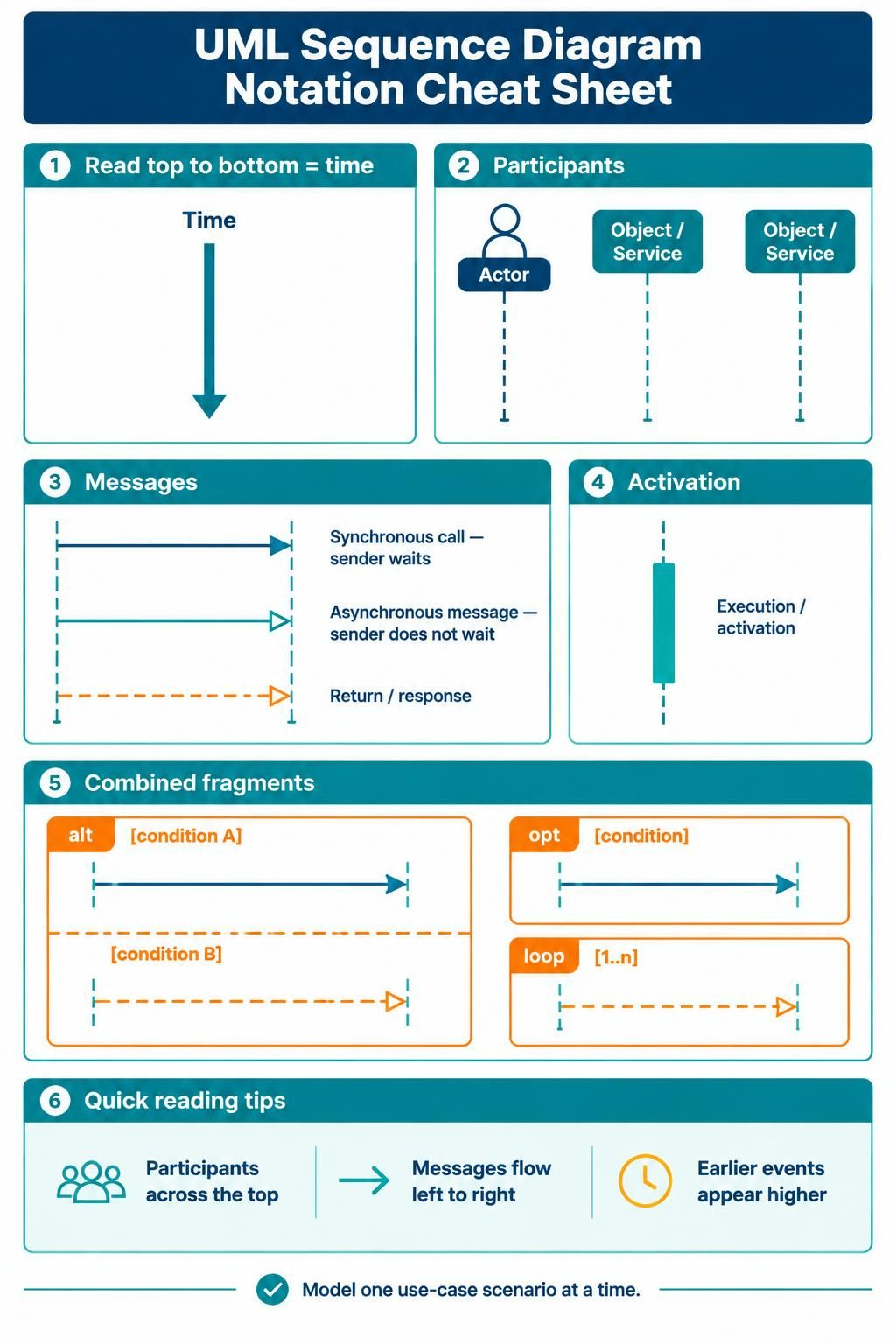
| Element | What it represents | Typical use |
|---|---|---|
| Actor | A person or external system interacting with the system | Customer, payment provider |
| Participant | A system, service, component, or object in the interaction | Checkout UI, Order Service |
| Lifeline | A participant’s existence during the interaction | Vertical dashed line |
| Message | A communication or interaction between participants | submitOrder() |
| Return message | A response or result | orderConfirmed |
| Activation | A period when a participant is performing work | Narrow rectangle on a lifeline |
| Combined fragment | A structured branch, repetition, or optional flow | alt, opt, loop |
Use participant names that match the level of the diagram. A system-level sequence diagram may show one system boundary between the actor and an external service. A design-level diagram can show internal components such as controllers, services, and repositories. Avoid mixing levels unless the extra detail helps answer a specific question.
Common message styles include:
-
Synchronous call: The sender waits for a result, often shown with a solid line and filled arrowhead.
-
Asynchronous signal: The sender does not wait for the receiver to finish, often shown with an open arrowhead.
-
Return: A response, often shown as a dashed line. Show returns when they clarify the scenario; they need not be drawn for every call.
Use labels that describe intent—authorizePayment(amount) or showConfirmation(orderId)—rather than vague labels such as process() or doStuff().
2. Use case approach: from goal to interaction
A use case describes a goal and the behavior needed to achieve it. A sequence diagram illustrates one scenario of that use case. A use case may need several diagrams if its alternate paths are important.
Use case approach: from goal to interaction
A use case describes a goal and the behavior needed to achieve it. A sequence diagram illustrates one scenario of that use case. A use case may need several diagrams if its alternate paths are important.
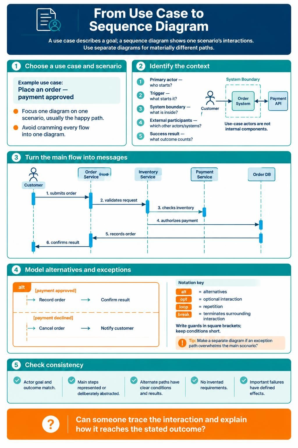
Step 1: Choose a use case and a scenario
Pick a use case with meaningful interactions, such as Place an order. Start with one clear scenario, usually the successful or “happy” path. Give the scenario a name, such as Place order — payment approved.
Don’t try to fit every use case, exception, and implementation detail into one large diagram. Create separate diagrams for materially different scenarios.
Step 2: Identify the trigger, participants, and result
From the use case, extract:
-
Primary actor: Who starts the scenario?
-
Trigger: What event starts it?
-
System boundary: What is inside the system being designed?
-
External participants: Which other systems or actors are involved?
-
Success result: What outcome counts as success?
Use case actors are not necessarily internal components. If a use case only says “the customer places an order,” you may need to decide whether the diagram should stop at the system boundary or expand into internal design components.
Step 3: Convert the main flow into messages
Take the use case’s main success steps and translate each into a message or a meaningful result. For example:
-
Customer submits an order.
-
System validates the request.
-
System checks inventory.
-
System requests payment authorization.
-
System records the order.
-
System confirms the result to the customer.
The diagram should show the interactions needed to make these steps happen, not merely copy the use case text onto arrows.
Step 4: Add alternative and exception behavior
Use UML combined fragments to express conditional or repeated behavior:
-
alt— alternative branches, such as approved versus declined payment. -
opt— an optional interaction. -
loop— repeated behavior, such as retrying a request. -
break— a branch that terminates the surrounding interaction in the scenario.
Put a short guard condition in square brackets, such as [payment approved]. For an alt fragment, label each branch with its condition. Use a separate diagram when the exception path becomes so involved that it obscures the main scenario.
Step 5: Check consistency with the use case
For every diagrammed scenario, confirm that:
-
The actor’s goal and the use case’s outcome still match.
-
The main-flow steps are represented or deliberately abstracted.
-
Alternate flows have clear conditions and results.
-
The diagram does not silently invent requirements.
-
Every important response or failure has a defined effect.
A useful review question is: Could someone trace this interaction and explain how the scenario reaches its stated outcome?
Step 1: Choose a use case and a scenario
Pick a use case with meaningful interactions, such as Place an order. Start with one clear scenario, usually the successful or “happy” path. Give the scenario a name, such as Place order — payment approved.
Don’t try to fit every use case, exception, and implementation detail into one large diagram. Create separate diagrams for materially different scenarios.
Step 2: Identify the trigger, participants, and result
From the use case, extract:
-
Primary actor: Who starts the scenario?
-
Trigger: What event starts it?
-
System boundary: What is inside the system being designed?
-
External participants: Which other systems or actors are involved?
-
Success result: What outcome counts as success?
Use case actors are not necessarily internal components. If a use case only says “the customer places an order,” you may need to decide whether the diagram should stop at the system boundary or expand into internal design components.
Step 3: Convert the main flow into messages
Take the use case’s main success steps and translate each into a message or a meaningful result. For example:
-
Customer submits an order.
-
System validates the request.
-
System checks inventory.
-
System requests payment authorization.
-
System records the order.
-
System confirms the result to the customer.
The diagram should show the interactions needed to make these steps happen, not merely copy the use case text onto arrows.
Step 4: Add alternative and exception behavior
Use UML combined fragments to express conditional or repeated behavior:
-
alt— alternative branches, such as approved versus declined payment. -
opt— an optional interaction. -
loop— repeated behavior, such as retrying a request. -
break— a branch that terminates the surrounding interaction in the scenario.
Put a short guard condition in square brackets, such as [payment approved]. For an alt fragment, label each branch with its condition. Use a separate diagram when the exception path becomes so involved that it obscures the main scenario.
Step 5: Check consistency with the use case
For every diagrammed scenario, confirm that:
-
The actor’s goal and the use case’s outcome still match.
-
The main-flow steps are represented or deliberately abstracted.
-
Alternate flows have clear conditions and results.
-
The diagram does not silently invent requirements.
-
Every important response or failure has a defined effect.
A useful review question is: Could someone trace this interaction and explain how the scenario reaches its stated outcome?
3. Example: Place an order
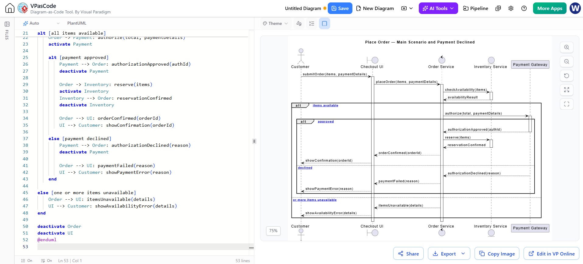
This example models one successful scenario and one alternative: payment is declined. It uses a boundary-style checkout participant, internal services, and external inventory and payment systems. The names and responsibilities are illustrative; adapt them to your actual design.
Reander with VPasCode tool for the sequence diagram using PlantUML:
@startuml
title 用户登录流程 (User Login Flow)

participant "User" as U
participant "System" as S
participant "Database" as DB

Note over U, DB: 这是一个专注于单一场景的交互模型

U -> S: 1. Login (发送登录请求)
activate S

S -> S: 2. Validate credentials (系统验证凭据)

S -> DB: 3. Get user data (获取用户数据)
activate DB
DB --> S: 4. User data (返回用户数据)
deactivate DB

S --> U: 5. Login result (返回登录结果)
deactivate S

@endumlThe diagram’s alt fragments make the decision points visible. The guards distinguish the branches, while the message labels show what each participant communicates. In a production model, you may need to specify whether inventory is reserved before or after payment authorization, how reservations are released on failure, and how timeouts or duplicate submissions are handled.
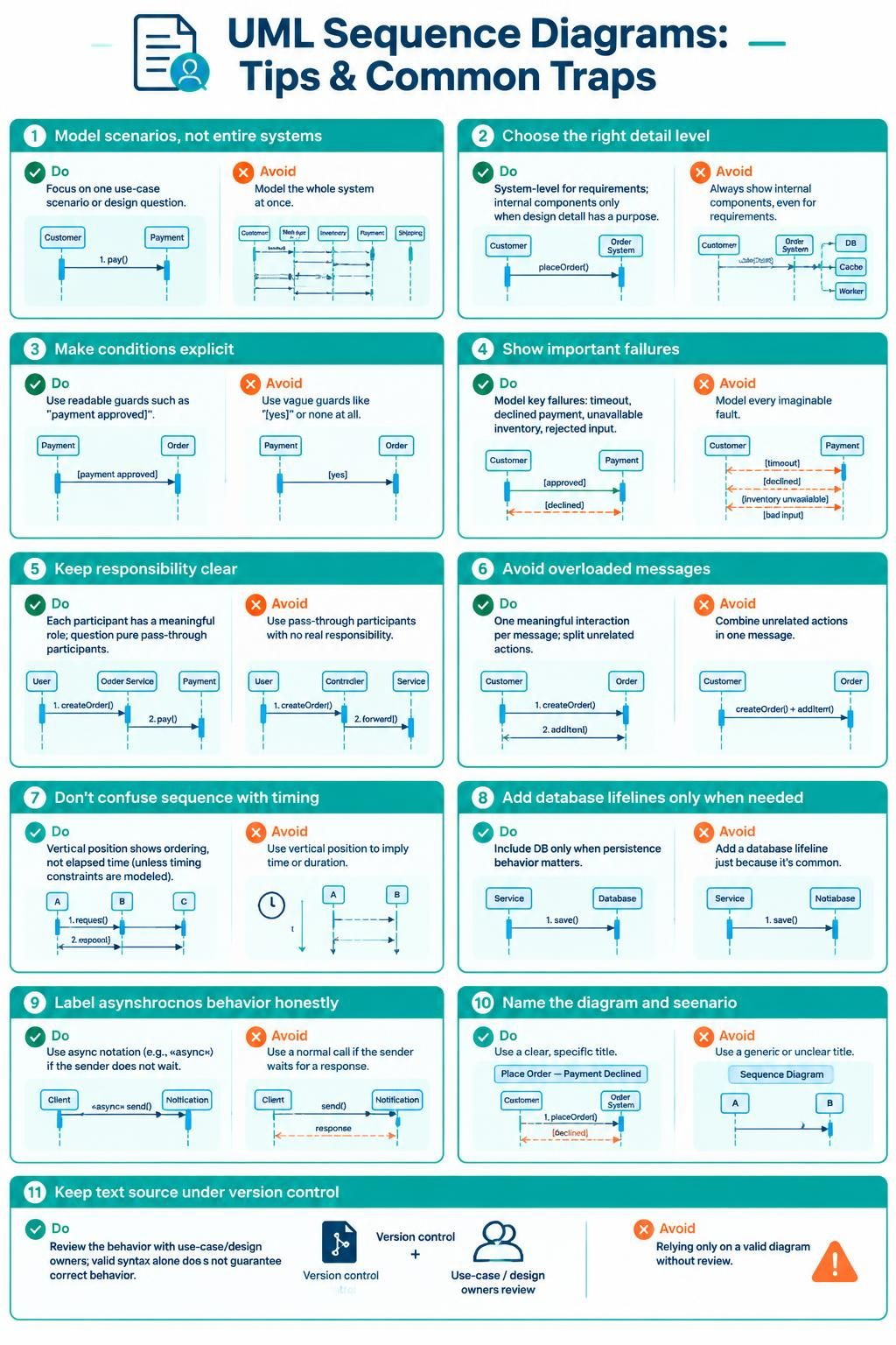
4. Tips and common traps
-
Model scenarios, not entire systems. Keep each diagram focused on one use case scenario or one design question.
-
Choose the right detail level. Requirements discussions usually benefit from a few system-level participants. Detailed design diagrams can show internal components, but should have a specific purpose.
-
Make conditions explicit. A branch without a readable guard is hard to interpret. Prefer
[payment approved]over vague labels like[yes]. -
Show important failures. Timeouts, declined payments, unavailable inventory, and rejected input often shape the design. Include the failures that matter to the scenario; don’t model every imaginable fault.
-
Keep responsibility clear. Each participant should have a meaningful role. If a participant only passes messages through, ask whether it belongs in this diagram.
-
Avoid overloading messages. A message should communicate one meaningful interaction. Split unrelated actions into separate messages when that improves clarity.
-
Don’t mistake sequence for a precise timing chart. Vertical placement shows ordering, not elapsed time, unless you explicitly add timing constraints or use a timing diagram.
-
Be careful with “database” participants. Show persistence calls when storage behavior matters to the design. Don’t add a database lifeline automatically to every diagram.
-
Label asynchronous behavior honestly. If a sender does not wait for a response, model the interaction as asynchronous rather than implying a synchronous call.
-
Name the diagram and scenario. A title such as “Place Order — Payment Declined” makes scope immediately clear.
-
Keep the source under version control. Text-based diagrams are reviewable and easier to compare than screenshots alone.
-
Review the diagram with the people who own the use case and design. A syntactically valid diagram can still encode the wrong behavior.
5. A practical Visual Paradigm workflow
A useful workflow is to go from requirements, to a draft diagram, to reviewed and maintained model artifacts:
-
Start with the use case. Write down the actor, preconditions, trigger, main flow, alternate flows, and postconditions. If those are unclear, the diagram will likely be unclear too.
-
Use the Visual Paradigm AI Diagramming Chatbot for a first draft or exploration. Describe the use case and ask for a sequence diagram for a specific scenario. The chatbot supports sequence diagrams and can generate related models, including deriving a sequence diagram from a use case; it also supports conversational refinement. Treat the result as a draft to review, not as proof that the behavior is correct.
-
Refine with focused prompts. For example: “Show the payment-declined alternative,” “Keep this at system-boundary level,” or “Add a retry only for transient payment timeouts.” Review the result against the use case after each change.
-
Edit the diagram as code in VPasCode. VPasCode supports PlantUML and other diagram-as-code formats, with editing and rendering in one environment. Visual Paradigm describes workflows for opening chatbot-generated diagram code in VPasCode for finer editing.
-
Use Visual Paradigm Desktop when you need fuller modeling and project integration. It can be used to refine diagrams in a visual modeling environment and connect the diagram to the wider project model. Visual Paradigm’s AI and product integrations vary by product and edition, so check your installed edition and current account access for availability.
-
Save and share the reviewed result. Keep the PlantUML source with the project where appropriate, and export or place the diagram in project documentation. VPasCode supports sending finished diagrams into Visual Paradigm OpenDocs for documentation.
Prompting AI effectively
A useful prompt gives the tool enough structure to produce a reviewable draft:
Create a UML sequence diagram for the “Place Order” use case. Show the main success scenario and a separate payment-declined alternative. Keep the Customer outside the system boundary. Use Checkout UI, Order Service, Inventory Service, and Payment Gateway as participants. Show only interactions needed to understand the flow. Use PlantUML.
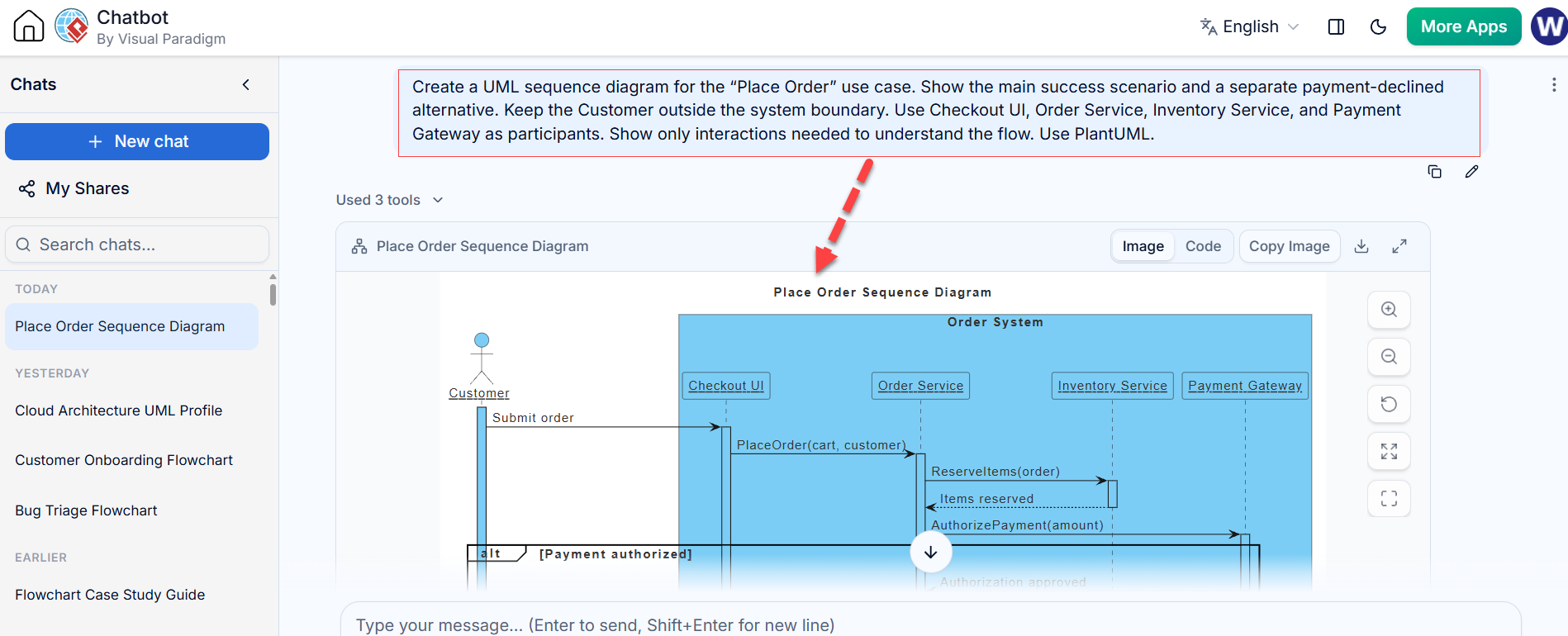
Then ask for one targeted change at a time. Specify the scenario, level of detail, participant names, and behavior you want added or removed. Afterward, check the messages, guard conditions, participant responsibilities, and error outcomes against the actual use case.
6. Quick quality checklist
Before sharing or baselining a sequence diagram, check:
-
The title names the use case and scenario.
-
The actor, system boundary, and participants are clear.
-
Messages read in the correct top-to-bottom order.
-
Important branches use understandable guards.
-
Failure outcomes are shown where they affect the scenario.
-
The diagram is at one consistent level of detail.
-
No message or participant implies an unconfirmed requirement.
-
The rendered diagram is readable and the source is saved.
A good sequence diagram is not the most detailed one. It is the smallest clear interaction model that helps its audience understand, review, or implement the scenario.
Conclusion
A UML sequence diagram is most effective when it connects a use case’s goal to a clear, traceable interaction. Start with one scenario, identify its participants and system boundary, then show the messages, decisions, and important outcomes needed to understand that flow. Keep the diagram focused, use guards and failure paths where they add clarity, and avoid detail that does not serve the reader.
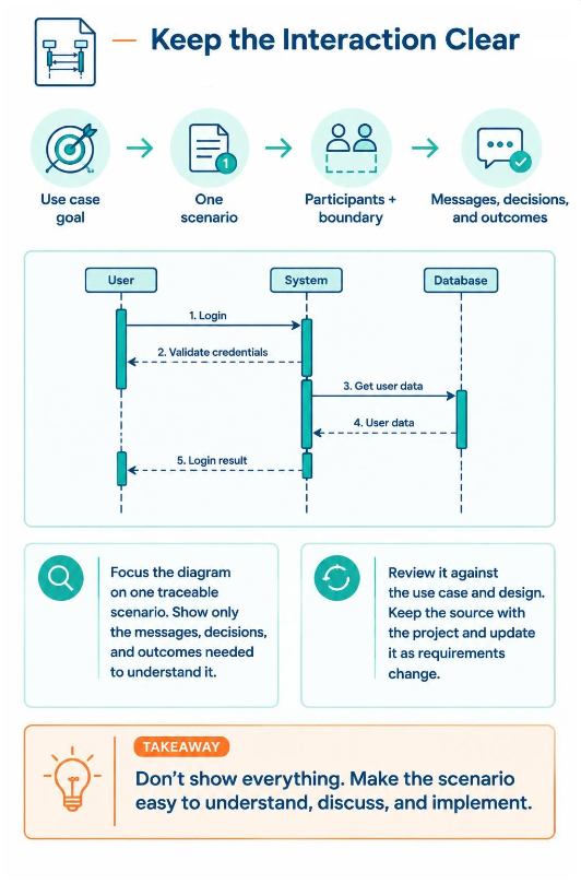
Treat the diagram as a model to review and maintain—not just a picture to produce. Check that it agrees with the use case and design, keep its source with the project, and revise it as requirements change. The goal is not to show everything, but to make the scenario easy to understand, discuss, and implement.